First of all, it is important to understand why water treatment is necessary also after the water enters an electrolyzer. Lack of or wrong design of water treatment in the electrolysis loop will lead to:
- Damage to the electrolyzer stack
- Unreliable operation with frequent unplanned stops
- Higher total cost of water treatment
- Increased water consumption
It is also important to note that while the electrolyzer stack accounts for 40–60% of the total capital cost of an electrolyzer system, water treatment constitutes only about 1% (see Figure 1), meaning that the problems can be dealt with in a cost-effective manner.
But why can’t we just improve the treatment of the water before it enters the electrolyzer to avoid treating the water inside of the electrolyzer?
Pollutants in the electrolyzer system originate not only from the feedwater but are also released from the electrolyzer itself. To eliminate pollutants from the water circulating inside the electrolyzer, a water treatment system must be added to what is typically referred to as a refinement loop.
To properly design this system, it is necessary to take into account how the electrolyzer influences the water quality:
- Modification of pollutants
Due to constant circulation, pollutants can be modified by the electrolyzer, giving rise to a more complex mixture of pollutants in the water.
- Concentration of pollutants
The electrolysis process concentrates any pollutants inside the electrolyzer. This happens because water is continually turned into hydrogen and thus removed from the system. As the degree of water utilization increases, so does pollutant concentration. For instance, if 90% of the water is converted to hydrogen, pollutant concentration will increase by a factor of 10, and if 99% of the water is utilized, pollutant concentration will increase by a factor of 100.
In practice, this means that the electrolyzer does not operate on ultrapure feedwater. Instead, it operates on a polluted process stream. Figure 2 illustrates how the electrolyzer changes the composition of the water inside the electrolyzer.
The formation and types of pollutants vary, depending on factors such as the electrolysis process type, electrolyzer operating conditions, and the water treatment equipment used to maintain water quality. This article focuses specifically on alkaline and PEM electrolysis, which are the two most prevalent electrolysis processes at the time of writing.
What is ultrapure water?
Water suitable for electrolysis is commonly referred to as ultrapure. Understanding the quality of ultrapure water for electrolyzers requires consideration of the specific electrolyzer technology. Different types of electrolyzers are sensitive to specific compounds in the water, requiring customized water specifications for each electrolyzer. Acceptable levels for problematic compounds are typically restricted to parts per billion (ppb).
Conductivity serves as a general measure for the maximum allowable ion concentration. Alkaline electrolyzers typically permit conductivity levels of 1–5 µS/cm, whereas PEM has a more stringent limit of up to 0.1 µS/cm. Additionally, it is often essential to establish limits for organics and silica, as these are not adequately addressed by conductivity measurements.
Maintaining water purity in alkaline electrolysis
In alkaline electrolysis, ultrapure make-up water is mixed with potassium hydroxide (KOH) to a concentration of around 25–30 wt%. The KOH provides conductivity as the electrolysis process is mediated by the hydroxide ion.
The highly concentrated alkaline electrolyte solution makes it very difficult to perform separation on the molecular and ionic level; however, it helps keep the solution clean. Due to the high concentration, most ions will tend to precipitate as either potassium or hydroxides salts due to salting-out effect. Looking at calcium (Ca) as an example, only 8 ng of Ca can be dissolved in one liter of 25 wt% KOH before it will precipitate as calcium hydroxide (Ca(OH)2).
Because of this, the main problem for alkaline electrolyzers when it comes to maintaining the water quality is the formation of particles that can clog the electrolyzer or lead to deposits and scaling in the system.
To remove the particles, a lye filter is used, typically integrated directly into the deionized-water/lye loop to treat the entire flow. This filter must be capable of withstanding the corrosive environment, high temperature, and the potential presence of molecular hydrogen.
Maintaining water purity in PEM electrolysis
PEM electrolyzers differ significantly from alkaline electrolyzers. Unlike their alkaline counterparts, they do not require the addition of electrolytes like KOH to the water. In PEM systems, a proton exchange membrane situated between the electrodes serves as the electrolyte. Consequently, ultrapure water is used in its natural state, without any added electrolytes. This allows for the treatment of water using ionic and molecular separation techniques to maintain its quality.
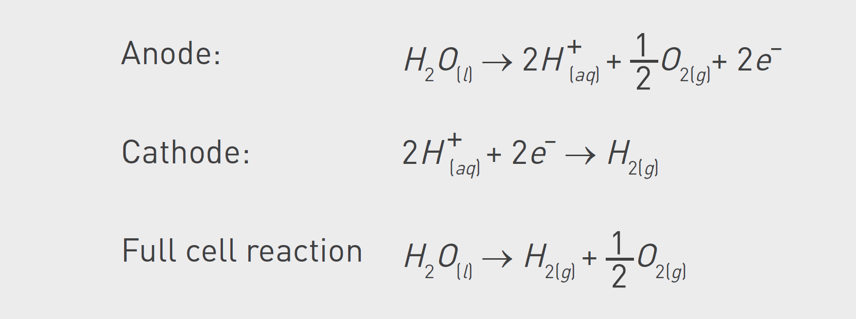
During electrolysis in a PEM cell, a very corrosive environment is created. The process is based on oxidizing water to protons at the anode, which are then reduced to hydrogen at the cathode.
In the process, fluoride ions are released from the electrolyzer and combined with hydrogen ions to form hydrofluoric acid. Due to the corrosive environment, the electrolyzer system can degrade and release ions harmful to the electrolyzer stack into the DI-water loop.
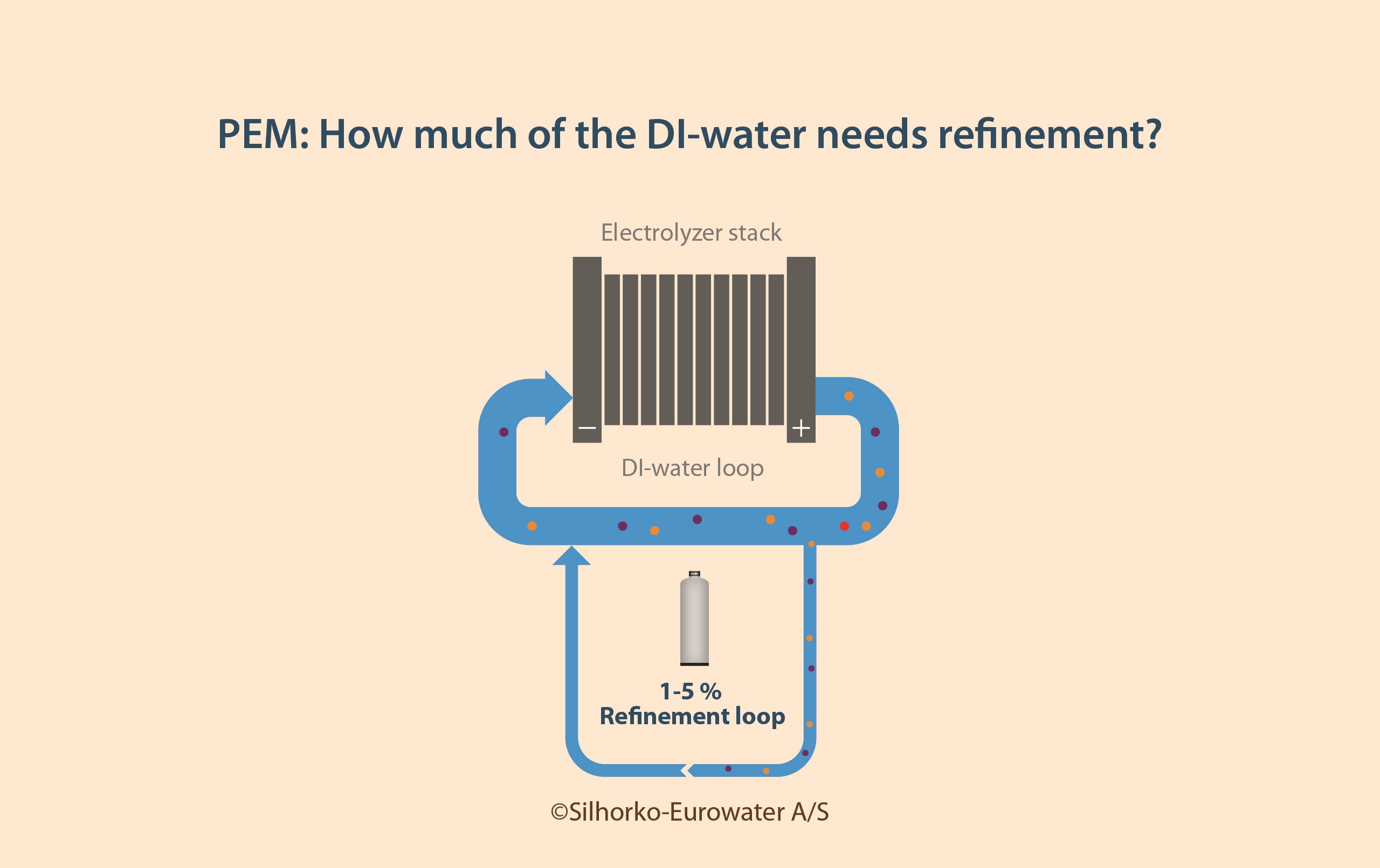
To prevent the accumulation of these harmful ions and molecules, the water must be continuously cleaned, which is done by treating a side stream of the DI-water loop in a refinement loop.
The most common approach is to treat the water with a polisher capable of deionizing the water, followed by a particle filter aimed at removing resin fines from the polisher. Some designs also include a UV lamp after the particle filter to disinfect the water, but this is typically unnecessary due to the very low risk of biofouling in electrolyzer systems.
The size of the refinement loop depends on a number of variables:
- Quality of the make-up water
- Leaching potential of materials used in the electrolyzer
- Electrolyzer operation conditions (e.g., temperature and pressure)
- Quality criteria within the DI-water loop
The quality criteria within the DI-water loop specify the maximum allowable steady-state concentration of pollutants. The lower the target concentration or conductivity in the DI-water loop, the larger the refinement loop must be.
As a general rule of thumb, the refinement loop in PEM systems should have a flow equal to 1–5% of the DI-water loop, as illustrated in Figure 5.
Conditions in the refinement loop are both corrosive and involve elevated temperatures, meaning that the water treatment system must be capable of effectively treatingthe water without being damaged by it.
Two technologies are typically considered for the polishing process: mixed bed ion exchange and electrodeionization (EDI), but currently, only one is deemed suitable.
Did you know?
The practical lower limit for conductivity in water at 25°C is 0.056 µS/cm. This is the background conductivity created by water molecules that constantly split to form hydrogen ions and hydroxide ions in the autoprotolysis of water. You can never get below this value.
Just 1 mg/L of sodium chloride (NaCl) will lead to a conductivity of 2.2 µS/cm.
Which polisher technology to use in PEM refinement loop?
Mixed bed and EDI use similar processes that rely on ion exchange to remove ions down to very low concentrations.
In a mixed bed, a vessel is filled with a mixture of anion and cation exchange resin beads. When the water passes the resin beads, the cation resin will adsorb any positively charged ions (e.g., metal ions) and release hydrogen ions. The anion resin will adsorb negatively charged ions (e.g., fluoride F–) and release hydroxide ions. The hydrogen and hydroxide ions will react and form water, leading to a solution virtually free of ions and only containing water molecules.
In EDI, ion exchange resin is combined with ion exchange membranes and electricity, facilitating continuous ion removal from the water.
Once the resin’s capacity in a mixed bed is consumed, it must be either chemically regenerated or replaced. In contrast, EDI systems can keep operating as the resin is continuously regenerated by electricity.
Today, the best available technology for PEM refinement is mixed beds relying on one-time-use resins. This is because the harsh environment inside the electrolyzer system requires special resins and ion-exchange vessels to operate safely. These special resins and materials are currently not available for EDI.
At present, regenerating the special resins is too risky, as this can lead to increased contamination of the resin, which degrades its capacity to treat the water to the required quality. However, with the expansion of green hydrogen plants, resin regeneration could become feasible, enhancing both economic and environmental sustainability. Similarly, the development of dedicated EDI systems for PEM electrolyzer refinement loops is likely, offering operational, economic, and sustainability benefits.
Summary
Maintaining the ultrapure water after it enters the electrolyzer stack is crucial for safe, stable, and long-term operation. Figure 6 sums up the learnings from this article.
Alkaline and PEM electrolyzers encounter distinct challenges due to their differing operational processes, necessitating specific solutions for each.
In the case of alkaline electrolyzers, a water treatment system is necessary to eliminate particles formed in the concentrated lye solution. This involves using particle filters tailored to the chemistry of the lye solution. On the other hand, PEM electrolyzers require the continuous removal of harmful ions from both the make-up water and the electrolyzer system itself. The current optimal solution for PEM involves using mixed bed ion exchangers with special one-time-use resins.
The various types of pollutants and different water treatment systems mean that for alkaline electrolyzers, the entire DI-water stream must be treated, while for PEM systems, only a smaller side stream of 1–5% of the flow requires treatment.
Not paying attention to the specific challenges outlined in this article for both PEM and alkaline electrolysis can lead to severe damage to the electrolyzer itself. As Figure 1 shows, failing to invest in proper water treatment can be costly. Therefore, it is safe to say that water treatment done right will not make the business case, but water treatment done wrong will break it.
About the author

Henrik Tækker Madsen, PhD, is a water treatment specialist working within the interplay between water and energy. He works as Application Development Manager at the water treatment company Silhorko-Eurowater A/S – part of Grundfos, where he leads the work on establishing industry-leading knowledge within various water applications, including electrolysis. Dr. Madsen is a chemical engineer with more than 10 years of experience in business development, sales, R&D and innovation.


