To accelerate the implementation of large-scale green hydrogen production, we must reduce production costs, also known as the levelized cost of hydrogen (LCOH). To achieve this, it is crucial to address both CAPEX and OPEX. CAPEX is particularly significant for electrolyzers that will operate based on variable renewable electricity sources, such as solar and wind. The intermittent availability of these electricity sources results in limited operating hours for the electrolyzers, which amplifies the relative impact of CAPEX on the LCOH.
Cost reduction
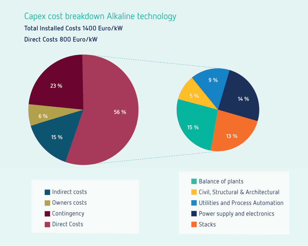
Cheaper and more efficient electrolyzers are being developed by start-ups and scale-ups. As more green hydrogen production plants are built, costs will be further reduced by automated electrolyzer production lines, replacing present-day manual production. However, the electrolyzer is just one part of the plant and typically accounts for approximately 13% of the plant’s CAPEX, as depicted in Figure 1. Even if the electrolyzer stacks were provided for free, a green hydrogen production plant would still be expensive!
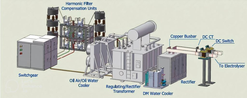
To further reduce costs, we need to look at other parts of the plant. One of these components is the power supply system, which has been estimated to account for approximately 14% of the overall costs. It is schematically depicted in Figure 2 and includes transformers that reduce the high voltages from the grid to the required levels for the electrolyzers (typically 200–600 V) and rectifiers that convert alternating current (AC) into direct current (DC). Additionally, it includes various other components such as harmonic filters and coolers. The power supply technology is considered mature, which, unfortunately, means that its cost reduction potential is limited compared to that of electrolyzers. In fact, increasing flexibility and grid requirements may result in rising costs, as more advanced filtering and rectification solutions are required. Consequently, the relative contribution of the power supply system to the total plant costs is likely to increase in the future.
Taking a system-level approach
What can we do to keep the costs of the power supply system under control? Firstly, we should move away from regarding the power supply system as a mere ‘slave’ to the electrolyzer, i.e., a system that just needs to deliver the desired DC current and voltage to the electrolyzer. The problem with this approach is that it can lead to high costs for the rectifier, e.g., when very high-quality DC current is required. Instead, we should adopt a systems perspective, focusing on optimizing the design of the combined rectifier and electrolyzer. While this approach may result in the electrolyzer receiving a slightly less perfect DC current, potentially leading to lower performance, this trade-off is outweighed by the cost savings achieved in the power supply system.
To be able to make the right decision at a system level, we need to understand all the key aspects of both the electrolyzer and the power supply system, and especially their interaction. Here we face a challenge: the electrolyzer is the domain of electrochemical engineers, whereas the power supply system is the domain of electrical engineers. Even though the names of these groups may be similar, they have very different expertise and as a result struggle to understand each other. Personally, I am an electrochemical engineer, and until a couple of years ago, I barely knew the difference between a rectifier and transformer, just assuming that the power supply system would deliver a perfect DC current to my electrolyzers.
We need to bring the worlds of electrolyzers and power supply systems together. This means that electrochemical engineers should receive proper training on power supply systems, and electrical engineers should also be trained on electrolyzers. Additionally, we should conduct more extensive research on the interface between the power supply system and the electrolyzer. There are few articles on this interface, and even fewer are co-authored by a combination of electrochemists and electrical specialists, which is desired to ensure high-quality work.
A first step: creating a combined rectifier-electrolyzer model
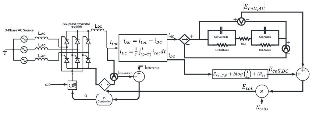
A few years ago, I started talking to one of my colleagues of the electrical engineering department. Together, we reached the conclusion that it would be nice if we could combine electrical and electrochemical models into one. So, that is what we started doing with the help of two bright master’s students. The resulting model is depicted in Figure 3.
The model combines a 6-pulse thyristor rectifier model and an electrochemical model consisting of two parts: a steady-state electrolyzer model that calculates the cell potential based on the average current, and a dynamic model that calculates the variation in cell potential from the variation in input current. The input values required for the electrochemical models were obtained from laboratory experiments. Furthermore, the combined electrochemical model was also experimentally validated in the laboratory, demonstrating its ability to effectively model potential responses within the millisecond range. Although the electrochemical model was originally developed for a small-scale laboratory electrolyzer, it can be easily adapted to effectively describe a large-scale industrial electrolyzer.
Efficiency modeling
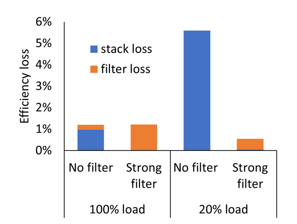
We used the model to determine efficiency losses caused by imperfect rectification, which occur in both the electrolyzer and the rectifier. In the electrolyzer, these losses stem from the current ‘ripples’ resulting from imperfect rectification of the 6-pulse rectifier. In the rectifier, losses occur due to a filter designed to mitigate these ripples.
Our modeling work revealed that a strong filter reduces efficiency losses in the electrolyzer but increases losses in the filter itself (see Figure 4). This necessitates a trade-off when determining the filter size. Additionally, the operating profile of the electrolyzer must be considered in this trade-off, as efficiency losses depend on the load of the electrolyzer.
Modern electrolyzer plants will not make use of 6-pulse thyristor rectifiers, but instead will use more advanced 12- or 24-pulse or insulated-gate bipolar transistor (IGBT) rectifiers. Therefore, the presented results are not directly relevant for these plants. Optimizing a filter was also not the objective of this work. Instead, it was to show the potential of this type of modeling. To really create value, more advanced rectifier models will need to be combined with electrolyzer models.
Making the right design choices
Modeling the interface between the electrolyzer and the power supply system can help in making the right design choices for the plant, especially when these models can be effectively coupled to cost models for both CAPEX and OPEX. This approach has the potential to assist in selecting the most suitable rectifier type (IGBT or thyristor-based) for grid-based electrolyzers and those directly connected to renewable energy sources. Furthermore, it can contribute to determining the optimal operating range and profile for the electrolyzer plant, since the power supply system can be one of the flexibility limiting factors.
Predictive maintenance
Yet, there is even more potential at the interface between the power supply system and the electrolyzer. In particular, more advanced rectifier systems (e.g., IGBT) can potentially serve as a tool to assess the state-of-health of an electrolyzer stack. While current state-of-health assessments are mostly limited to stack and cell potential measurements, an advanced rectifier could open the way to measurements that are similar to electrochemical impedance spectroscopy, a strong electrochemical technique that is currently mostly confined to the laboratory scale due to its relatively high costs. Ideally, this could enable the prediction of the remaining lifespan of an electrolyzer stack before a decline in performance. Nevertheless, achieving this will still require extensive research.
There is really a lot of POTENTIAL if we bring the worlds of electrolyzers and power supply systems together!
References


