By Davi Correia, Senior Mechanical Engineer
Case Study
Hydrogen (H) is the first element of the periodic table. If one remembers their chemistry lessons, they know that the chemical elements are arranged in order of increasing atomic number; and that the atomic number is somewhat related to the size of an atom. As hydrogen is the first element in the periodic table (atomic number 1), it comes as no surprise that it is a very small element as well as the lightest. As a consequence, hydrogen can leak easily. Moreover, high pressures are required to achieve useful energy densities for automotive applications.
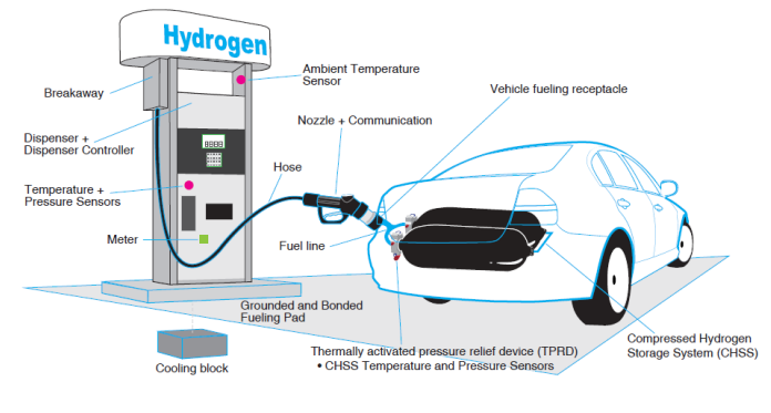
From a distance, a hydrogen fueling station looks very similar to a conventional one (see Figure 1); there is a dispenser and a flexible hose assembly that needs to be connected to the vehicle’s tank. However, upon closer inspection, there is a noticeable difference between the hoses.

A hose assembly for hydrogen delivery resembles more of a fire hose than a conventional gasoline fueling one. Hoses for hydrogen are thicker, heavier, and use a nozzle with a locking mechanism; the reason for this is pressure.
Hoses for gasoline or diesel delivery are rated for a maximum of 10 bar. When attached to the tank, they convey a liquid in a very similar way to how one would pour a glass of water from a jar – if distracted, it is easy to overflow and cause a spillage. In contrast, hydrogen hoses operate with a gas and can handle a much higher pressures; 350 bar for buses (and other heavy-duty applications) and up to 700 bar for light vehicles. In order to accommodate these pressures, the hose requires extensive reinforcement layers; making it heavier and thicker, see Figure 2.

The reason for a locking mechanism on the nozzle lies with the fact that the hydrogen being delivered is a gas, see Figure 3. The dispenser has the gas at a certain pressure (700 or 350 bar), which is then equalized with the pressure in the tank. As gas leaking from the connection wastes hydrogen, and also poses a safety risk the connection between the hose and the tank has to be secure. It works like this: a Toyota Mirai, for example, has a tank capable of holding approximately 5 kg of H2 at 700 bar; but if the tank is half-full, and you connect a 350 bar hose, you will not be able to fill up the rest. As the pressures in the dispenser and in the tank will be the same, no hydrogen will flow.1 In this situation, the tank you connect to would need to have a minimum of 700 bar to fill the car tank.

Material selection
Material selection for the inner tube poses some interesting challenges for the designer. Hydrogen molecules are very small and prone to leak easily through cracks, poor connections, or even some solid materials, as opposed to other common gases at equivalent pressures. Although hydrogen is generally non-corrosive and does not react with the materials used for hoses, at certain temperature and pressure conditions it can diffuse into a metal lattice causing a phenomenon known as ‘hydrogen embrittlement;’ this ultimately causes the steel reinforcement to fail.
Fuel cells are also very sensitive to contaminants and the inner tube material should not be a source of them. “Contaminants derived from fuel cell system component / structural materials, lubricants, greases, adhesives, sealants, and hoses have been shown to affect the performance and durability of fuel cell systems.”2
To ensure the integrity of the hose, hoses for hydrogen delivery should be assembled by the manufacturer and pressure tested to 1.5 times the rated pressure. They should be documented with serial number, test pressure, test date, and first date of service. It is highly advised that hydrogen hoses assemblies should also “be discarded after 12 months of use or immediately after any mechanical abuse such as a breakaway incident.”3
Final thoughts
The general public will be responsible for handling hoses and nozzles during refueling. Considering the pressures involved and the characteristics of the gas, it comes as no surprise that hydrogen stations are subject to strict regulation and standards. Some of the codes applicable in the United States are:
- NFPA 2 – Hydrogen Technologies Code
- ANSI/CSA HGV 4.2-2013 – Hoses for Compressed Hydrogen Fuel Stations, Dispensers and Vehicle Fuel Systems
- ISO 19880-5:2019 Gaseous hydrogen — Fueling stations — Part 5: Dispenser hoses and hose assemblies
Moving forward, it will be important to understand the unique requirements of hydrogen hoses and how to safely and efficiently maintain and operate them.
About the Author

Davi Correia is a Senior Mechanical Engineer who has worked at a major Brazil-based oil company for the last 15 years. Correia is part of multi-disciplinary team that provides technical support for topside piping and equipment of production platforms. During this period, he began to work with materials and corrosion, and later moved to piping and accessories technology, where he has become one of the lead technical advisors on valve issues.
Correia was part of the task force that revised the IOGP S-562 standard, and wrote the S-611 standard. Correia has a master’s and a doctor’s degree in welding by the Universidade Federal de Uberlandia.
- https://www.toyota.com/content/ebrochure/2021/mirai_fueling_V11.pdf
- Bahman Zohuri, Hydrogen Energy: Challenges and Solutions for a Cleaner Future, Springer Nature, 1st ed. 2019, ISBN-10: 3319934600
- Hydrogen Fuel Cell Engines and Related Technologies Course Manual, Module 10: Maintenance and Fueling Facility Guidelines, available at https://www.energy.gov/sites/default/files/2014/03/f11/fcm10r0.pdf
- https://h2tools.org/sites/default/files/2019-08/paper_256.pdf
- https://www.bridgestone.com/technology_innovation/hydrogen_hose/
- https://www.eia.gov/energyexplained/hydrogen/use-of-hydrogen.php
- Schneider, J. et al, Hydrogen Fueling Standardization: Enabling ZEVs with “Same as Today” Fueling and FCEV Range and safety, available at: https://h2tools.org/sites/default/files/2019-08/paper_256.pdf
- https://www.energysage.com/electric-vehicles/charging-your-ev/charging-a-tesla/
- Hydrogen Fuel Cell Engines and Related Technologies Course Manual, Module 4: Fuel Cell technology, available at https://www.energy.gov/eere/fuelcells/downloads/hydrogen-fuel-cell-engines-and-relatedtechnologies-course-manual


