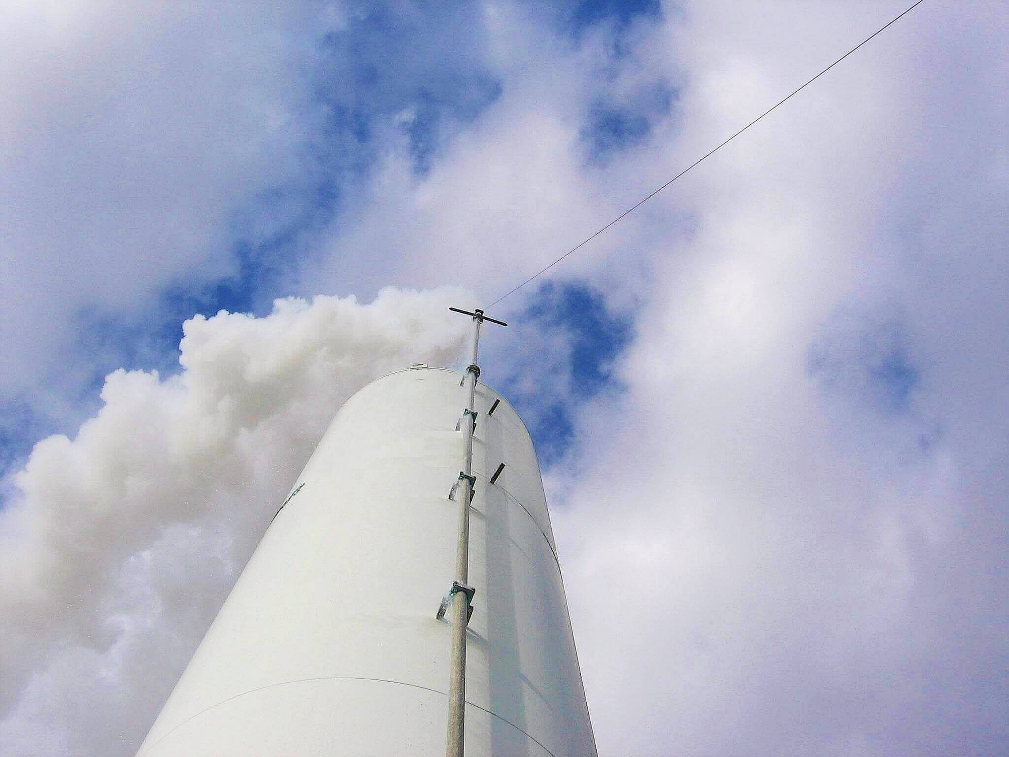
Vent systems are used to safely release hydrogen during normal and abnormal events such as high-flow relief device operation. When properly designed and installed, these systems reduce the effects of fire, asphyxiation, and fog (cold gas released from a liquefied hydrogen tank) on people, equipment, and the environment. Vent system designs are based on the properties of hydrogen. For example, because hydrogen is extremely buoyant, has low ignition energy, and can condense water vapor in the air from LH2, vent systems are designed to move hydrogen away from ground level for safety purposes. Typical equipment connected to a vent system can include pressure relief devices, purge and vent valves, bleed valves, and any opening that can vent hydrogen under operation or maintenance.
Unfortunately, the configuration of hydrogen vent systems may not be considered during the initial design or not included in the process hazard assessment (PHA). This can lead to vent stack damage or failure and hydrogen being discharged to undesired locations. It is essential that vent systems be designed by qualified engineers or designers. Designers need to consider the following:
- Process flow parameters (including maximum pressure, peak flow, maximum or minimum temperature, and composition)
- Materials of construction
- Supports
- Location
- Hydrogen operations
- Vent outlet piping design
- Expansion/contraction
- Flares or flame arrestors
- Grounding
- Purge gases
These design considerations are critical to the safe operation of the vent system and preventing vent system failure. Additionally, the design parameters (e.g., vent diameter, vent supports, interaction with other streams) must be evaluated for each process stream entering the vent system.
Improper designs that can cause vent system failure include:
- Incorrect supports
- Incorrect piping expansion/contraction
- Joints or vent system components with melting points below the hydrogen flame temperatures
- Undersizing the vent system
- Incorrect vent stack termination
Failures include:
- Overpressurization
- Plugging the vent system
- Air ingress during a release
- Interaction between flow streams
- Liquid air or ice issues as a result of incorrect installation
- A hydrogen release adversely affecting people or property
Clearly, many potential failures for a system can be (and often are) overlooked in the design and PHA for a hydrogen system.
Vent system incidents
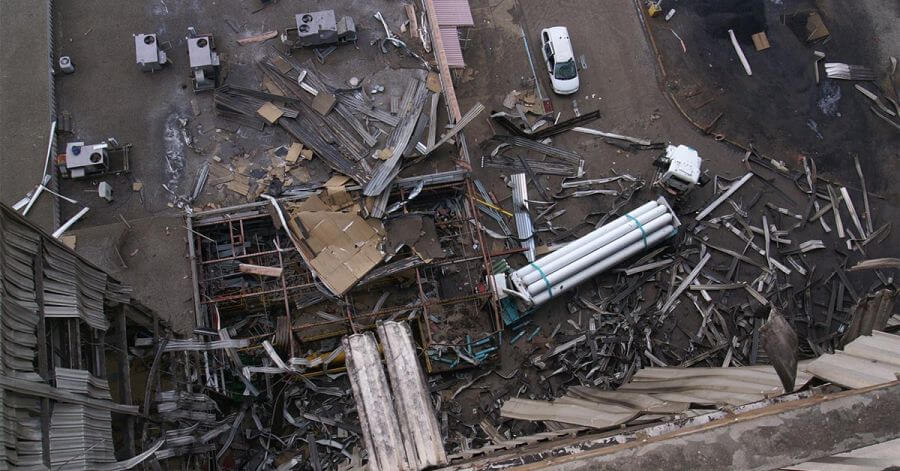
Improper design of vent systems has caused injury and death and damaged property.
On 8 January 2007, a hydrogen release killed one person and injured eight others at the Muskingum River Power Plant in Beverly, Ohio, and caused substantial damage to the facility. The incident was caused by the hydrogen vent stack failing within the building in response to a change in the direction of the hydrogen flow when the safety device was activated.
In 1974 in Lubbock, TX, an LH2 tank exploded when the local fire department sprayed water directly on the end of the only vent stack, plugging the stack. This destroyed the LH2 tank, injured several people, and damaged property.
On 11 February 2018, an incorrectly rated rupture disc prematurely opened, damaging the vent systems and causing a fire on the back of a hydrogen trailer at Diamond Bar, CA. During the event, the vent system piping was also pulled out of the compression fittings due to incorrect installation.

The Center for Hydrogen Safety (CHS), a global membership organization dedicated to promoting hydrogen safety and best practices worldwide, has had extensive discussions among its members and the Hydrogen Safety Panel about vent design and other hydrogen safety practices. As a result of these discussions, CHS has developed a list of the top 10 considerations for designers to avoid the most common mistakes that can result in vent system failure.
1. Overpressurization
The system should be designed for a minimum pressure of 40 bar, as recommended by the European Industrial Gas Association (EIGA) 211/17, Hydrogen Vent Systems for Customer Applications. Additionally, it is a best safety practice to design the pressure rating of the piping at the highest rated pressure entering the vent system.
2. Plugging/blocking the vent system
The vent system should be designed to avoid freezing from the introduction of moisture or other obstructions (such as insects or bird nests). For either an LH2 or a GH2 vent stack, ensure water cannot collect in the vent stack by using a water barrier cap that will open only during required hydrogen releases. If water can collect in the vent system, such as in a cold LH2 stack interaction with humid air, provide a monitored water collection chamber at least 0.6 m (2 ft) below the cold hydrogen inlet at the bottom of the vent stack and ensure that it provides enough volume to collect water from the vent, typically several gallons for small vent stacks. All piping from any relief valve or valve outlet should slope downward with no liquid collection points between the components and the vertical vent stack. Signs should be placed near the vent system directing the fire department not to spray water on the vent stack outlet. Only helium should be used for LH2 systems if a purge gas is required, since it is the only gas that will not solidify at LH2 temperatures.
3. Incorrect supports
The design of supports for vent stacks should consider reaction forces (especially from pressure safety relief valve activating), local wind, and seismic forces, and ensure that the supports are designed for vent system expansion/contraction due to temperature changes. The end of the vent stack must be supported such that the reaction forces sum to zero. This is accomplished by vertical flow upward or a tee stack that equalizes the flow through both opposing legs of the tee. ‘L’ type or single-exit horizontal flow direction vent stacks are discouraged due to the large directional reaction forces. Even with tee stacks, harmonic motion can occur if the top vent stack outlet supports are more than 0.5–0.6 m (1.5–2 ft) below the top of the vent stack.
4. Incorrect piping expansion/contraction
Consider pipe and fitting expansion/contraction due to temperature changes. Make sure piping connected to the vent piping (such as conduit or propane for flaring) expands or contracts at the same rate as the hydrogen piping or the attached conduit/piping is designed to move independently of the hydrogen vent stack. Installation errors have caused vent stack failures from changes in flow direction (forces on elbows) and the use of compression fittings on thick walls and/or large-diameter tubing being incorrectly installed. Changes in flow direction create reaction forces within the piping that can result in failures. Typically, vent systems are not pressure tested after installation; thus, incorrectly connected joints may fail during the operation of the vent system. An example of this is swaged tubing on thick-walled or large-diameter piping. This type of connection requires hydraulic machinery to ensure a correct connection with good mechanical integrity.
5. Incorrect temperature rating for joints or vent system
Ensure the melting point for the joints and vent system components is above the hydrogen flame temperature during a release. This is especially a risk for plastic piping and copper-brazed joints. Welded 304 or 316-type stainless steel is the recommended material for the vent system. Plastic, cast iron, ductile or malleable iron, and high silicone should be avoided. Materials with low melting points (i.e., aluminum, copper, brass, and bronze) are not recommended because of their reduced strength at high temperatures. Carbon steel and many polymers are not suitable materials for LH2 hydrogen systems with operating temperatures below -29°C (-20°F).
6. Air ingress during a release
Ensure there are no openings in the vent system that can pull air into the vent stack during a flow event (i.e., from a venturi effect), which may result in a fire or deflagration in the vent stack.
7. Undersizing the vent system
Vent systems should be designed for the maximum peak flow at the operating pressure of every stream that can flow simultaneously. The design should address the distance and pressure drop of each flow stream
8. Interaction between flow streams
Ensure any interaction between the flow streams is considered for all the design parameters. For example, combining multiple hydrogen streams into one stack is common. Designers should ask whether a single vent stack is acceptable or if multiple vent stacks are needed. Operating conditions should be evaluated in this instance. In the case of two streams – e.g., one with a pressure of 700 barg and the other at 12 barg – two stacks are recommended. Another scenario may be combining GH2 at cold temperature (from an LH2 source) with a stream of GH2 at ambient temperature that has nitrogen gas for purging. This scenario will likely require separate vent stacks to ensure nitrogen doesn’t freeze solid and plug the vent stack.
9. Incorrect vent stack termination and release flow
The vent stacks should direct the flow of hydrogen upward and be designed to minimize reaction forces at the top of the vent stack. Refer to the vent stack design criteria within EIGA and Compressed Gas Association (CGA-North America) documents for details. These stacks should be located to ensure that a hydrogen release does not harm people or damage property. Vent stack outlets should be located outdoors, typically at a minimum elevation of 3 m (10 ft) for GH2 and 7.6 m (25 ft) for LH2. These elevations should be increased if roofing and adjacent buildings or structures are nearby. Refer to local codes for specific required heights and allowed locations.
10. Not considering liquid air or ice
Oxygen-rich liquid air and ice can form on piping and supports when flowing LH2 or cold hydrogen gas from an LH2 source. The oxygen-rich liquid air can cause flammable materials (e.g., asphalt) to burn or explode. Extreme cold temperatures can also damage concrete and cause embrittlement and failure of surrounding supports that are not rated for the temperature, such as carbon steel. Flowing LH2 or cold hydrogen gas from an LH2 source can result in oxygen-rich liquid air and ice forming on the piping.
Other design criteria
- Grounding. To minimize ignition sources, the system (including the vent stack) and the delivery vehicle should be grounded.
- Flaring. Unless a steady flow of hydrogen is continually vented, flaring is not recommended. Flaring requires a constant velocity and controls to ensure that the flare is not extinguished and air is not allowed to backflow into the vent stack.
- Inert gases. Inert gases are not typically used for extinguishing fires in a hydrogen vent system. If a fire occurs at the top of a vent stack, the best action is to isolate the source or let the hydrogen fire burn out. Putting the hydrogen fire out without isolating the source allows a build-up of hydrogen that can lead to reignition and increases the risk of an explosion.
- Mufflers or silencers. Silencers are usually not used due to high-pressure drop at the required flow rates. Codes such as EIGA 211/17, Hydrogen Vent Systems for Customer Applications expressly prohibit the use of silencers.
In conclusion, many conditions must be considered during design and verified during installation. Observing best safety practices and sound engineering principles and performing a thorough hazard review will minimize the potential for injury or property damage and bolster stakeholder confidence in hydrogen systems.
About the CHS
Founded in 2018, the Center for Hydrogen Safety (CHS) is a non-profit, unbiased corporate membership organization that promotes the safe operation, handling, and use of hydrogen and hydrogen systems across all installations and applications. A global technical community within the American Institute of Chemical Engineers (AIChE), the CHS builds upon the technical expertise embodied by AIChE, its Center for Chemical Process Safety (CCPS), and partnering organizations to identify and address concerns regarding the safe use of hydrogen as a sustainable energy carrier, in commercial and industrial applications, and in hydrogen and fuel cell technologies.
A trusted and highly respected resource, the Hydrogen Safety Panel (HSP) is a pioneer in reducing knowledge barriers to hydrogen fuel cell deployment and enabling timely technology adoption by cities and communities. Building on its diverse knowledge, rich experience, and technical objectivity, this not-for-profit expert panel utilizes safety reviews, research, information dissemination, and training to help government agencies, industry and other stakeholders ensure that hydrogen is safely stored and handled.


