By Henrik Tækker Madsen, Application Development Manager, Silhorko-Eurowater – A Grundfos Company
To have a qualified discussion about the use of water for green hydrogen production, we first need to define what we mean by ‘water’.
In the production of green hydrogen, it is necessary to distinguish between three types of water:
- Ultrapure water (used as a feedstock for the electrolyser)
- Cooling water
- Raw water
The quantity of ultrapure water used for electrolysis will be different from that of raw water extracted from the environment, and the quality of ultrapure water and cooling water is also different. Therefore, we need to deal with each one separately. Let’s first look at ultrapure water.
What is ultrapure water?
Water suitable for electrolysis is commonly called ultrapure, but what is to be understood by this label?
Several parameters influence what quality water must have to be suitable for electrolysis. These include the type of electrolyser, electrode material, system design and even brand of electrolyser.
Add to this that each of the ions and molecules in water will affect the electrolyser differently. Some can increase OPEX because of corrosion or increased need for cleaning, while others can lower the electrolyser efficiency and/or irreversibly damage and degrade the electrolyser.
With so many variables and effects, it is no surprise that water treatment is often tailored to the specific project, making it very difficult to come up with a unified standard for water quality for all electrolysers.
One strategy that electrolyser manufacturers can follow to simplify the issue is to set the requirements for conductivity sufficiently low to ensure that the concentration levels of problematic ions and molecules will in all certainty be below the electrolyser requirements. A good starting point can be <1 µS/cm for standard alkaline electrolysers, and <0.1 µS/cm for PEM electrolysers and alkaline electrolysers relying on advanced electrodes. However, it is worthwhile to remember two things: firstly, water treatment constitutes a relatively minor part of the total CAPEX of a hydrogen plant, and secondly, no electrolyser was ever damaged by using water that was too clean. Ensuring high quality and reliability in the water treatment may thus be the best investment to be made for an electrolyser system.
Consumption of ultrapure water
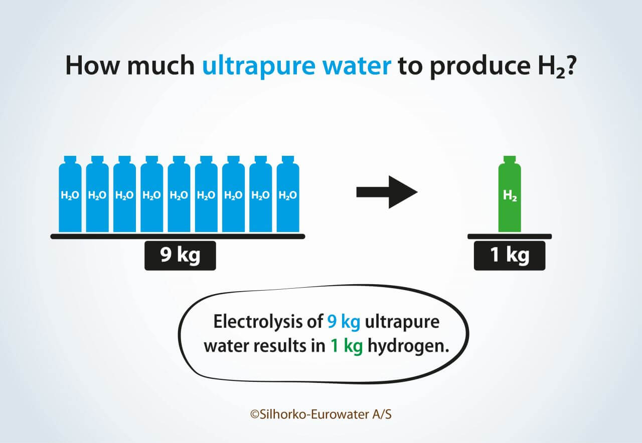
We can accurately calculate the amount of ultrapure water required for production of green hydrogen, using the atomic composition of water, H2O. Since oxygen is 16 times heavier than hydrogen, it is responsible for 89% of the mass of water, which means that 9 litres of water is needed to produce 1 kg of hydrogen (Figure 1). This ratio can be quite useful to determine the water requirements for a specific production capacity of hydrogen. For instance, production of 100,000 tons of green hydrogen per year will consume 900,000 m3 (tons) of ultrapure water.
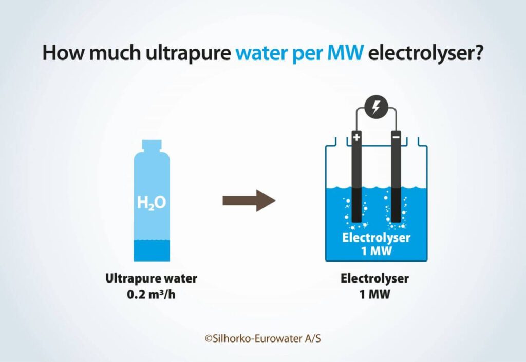
This approach tells us how much water is needed on average, but it will not tell us about the rate of water consumption (m3/h), which is required for dimensioning the water treatment system. Here, we need to look at the electrolyser power rating (MW). The power rating will determine the rate at which hydrogen is produced and thus the rate of water consumption. The amount of ultrapure water needed per MW depends on how much energy the electrolyser needs to convert the 9 L (kg) of ultrapure water to 1 kg of hydrogen. Most electrolysers consume 45–55 kWh per kg of hydrogen, which means that 0.16–0.2 L of ultrapure water is required per kWh, or 163–200 L/h of ultrapure water is required per MW of electrolyser capacity.
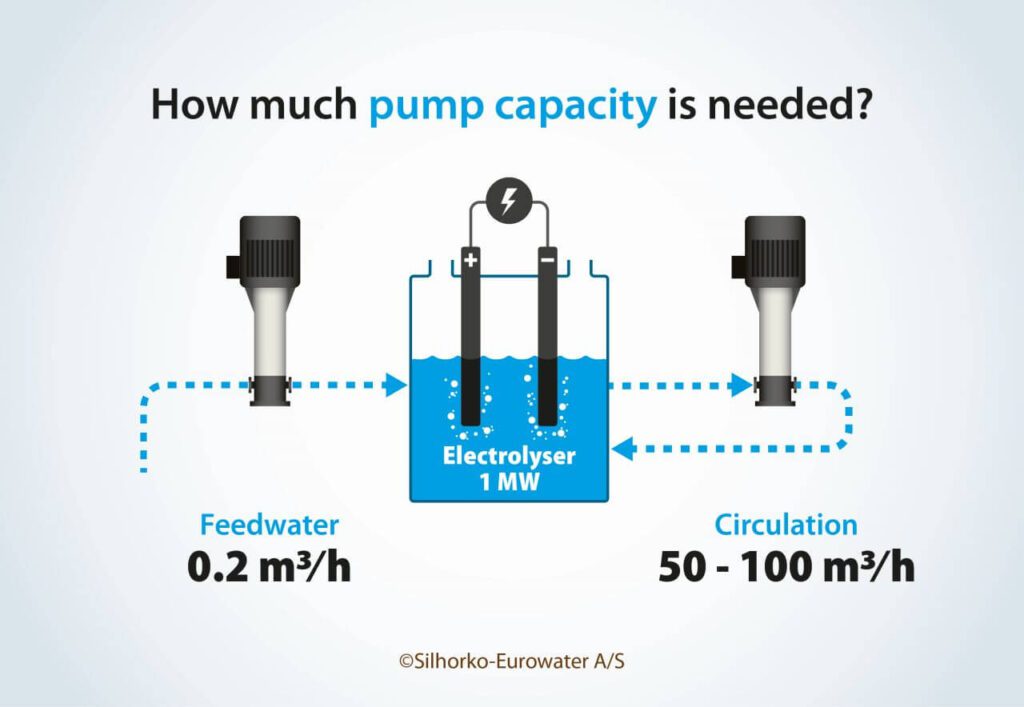
In my experience 200 L/h has proven to be an excellent rule of thumb as a first estimate of the requirements for ultrapure water (Figure 2). Thus, a 10 MW plant needs 2 m3/h, and a 1 GW plant needs 200 m3/h of ultrapure water.
Consumption of cooling water
While the consumption of ultrapure water as a feedstock will always be part of a green hydrogen facility, it is more difficult to give a precise evaluation of the consumption of cooling water. Many of the smaller projects that are realised today are based on dry cooling, while the very large electrolyser systems currently in planning may seek to integrate the waste heat into other water-based infrastructure systems such as wastewater treatment plants and district heating systems. Also, offshore-based systems may rely on the use of seawater for cooling.
For projects where a water-based cooling system is chosen, the specific design of the cooling solution will determine the water usage. For an evaporative cooling tower, relevant parameters include the starting water quality, the ratio between conductive and evaporative cooling, drift ratio, and concentration factor. All these factors make it complicated to come up with an accurate number, but to get a first estimate, a good rule of thumb is that 400 L/h of cooling water is needed per MW of electrolyser capacity, or roughly twice the amount required for electrolysis.
It is important to keep in mind that cooling water and water for electrolysis will have very different quality requirements.
Consumption of raw water
To determine the impact of a green hydrogen system on the local water systems, it is necessary to focus not only on the consumption of ultrapure water, but also on how much water must be taken from the raw water source to produce the ultrapure water.
Water can come from many sources. For most of the smaller projects seen today, water from the drinking water network is used. However, as hydrogen plants increase in size, this approach becomes unsustainable, and water must be sourced from elsewhere.
The three most common raw water sources for large-scale hydrogen projects are: groundwater, treated wastewater, and seawater. From the perspective of a water treatment system, surface water from rivers and lakes will in many ways be similar to treated wastewater, so these can be considered one.
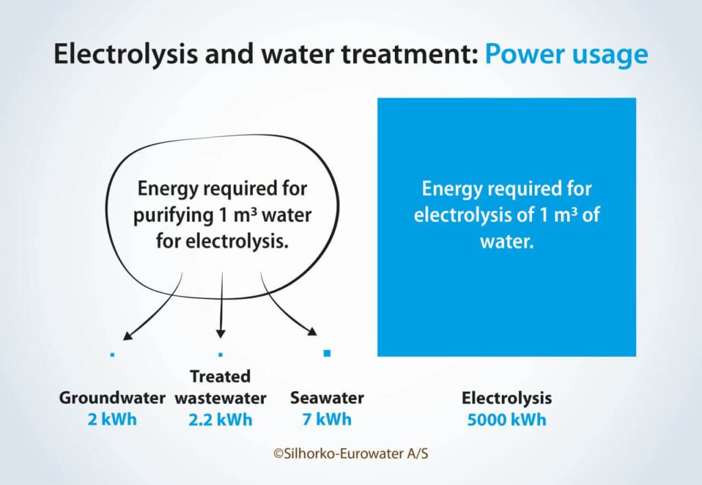
Each type of raw water will require different water treatment systems, and this affects how much raw water must be extracted. Of these, you need to extract the least raw water when using groundwater and the most when using seawater (Figure 3). Extraction of treated wastewater will be similar to that of groundwater.
The differences stem from the recoveries that can be obtained in the initial pretreatment of each raw water source before it is polished to ultrapure quality. For groundwater, standard filtration can reach very high recovery values, >98%. Treated wastewater filtered with ultrafiltration will typically have a slightly lower recovery of 90–95%. For seawater desalination, recovery is normally limited to 40–50% due to increasing osmotic pressure. The treatment to ultrapure quality comes with its own recovery, typically 75%.
With these rule-of-thumb numbers, it is possible to quickly estimate the water requirements for a given hydrogen project. The same electrolyser designed to produce 100,000 tons of hydrogen will require 900,000 m3 of ultrapure water and will need to extract 1,200,000 m3 of groundwater, 1,300,000 m3 of treated wastewater or 3,000,000 m3 of seawater.
Often, concern about the energy consumption of the water treatment process is brought up for discussion, especially when talking about seawater desalination. However, it is important to remember that while water treatment must overcome the attractive forces between water molecules and ions, electrolysis must overcome the strong covalent bonds between the atoms in the water molecules. As seen in Figure 4, turning seawater into ultrapure water may require 3–4 times as much energy as using groundwater or treated wastewater, but it is still only around a thousandth of the energy required for electrolysis.
Production of ultrapure water
The process from raw water to ultrapure water can be divided into two basic steps:
- Pretreatment of raw water
- Polishing to ultrapure standard
The role of the pretreatment system is to make the raw water suitable as a feed source for the polishing system. This means bringing the water to a state where it resembles city water quality. The type of pretreatment system depends on the source of water as each will come with their own challenges. Groundwater contains dissolved redox-active species such as iron and manganese, which can precipitate in and clog the polishing system. These can be effectively removed using aeration and sand filtration. For treated wastewater, the primary concern are particles, organics, and microorganisms. Here, ultrafiltration in combination with UV can be used to bring the water to a suitable quality. Seawater primarily requires removal of salts, but also of particles and dormant microorganisms. Using standardised reverse osmosis (RO) desalination is sufficient.
Once the raw water has been pretreated, we need to address the following issues to turn it into ultrapure quality:
- Content of ions – conductivity
- Hardness
- TOC
- Silica
- Gasses
To remove the bulk of the ionic load, RO is used. The membrane blocks ions, molecules and particles and will therefore also remove organics (TOC) and silica. To reach sufficiently low concentrations, it is often necessary to employ a double pass RO system, where the permeate from the first RO process is filtered again in a secondary RO system. For the RO system to operate properly, the water must first be conditioned to avoid scaling and damage to the membranes. If there is free chlorine in the water, this must be removed using active carbon, to avoid oxidation of the selective layer of the membrane. Hardness due to ions such as Ca and Mg can cause scaling and limit the recovery rate. This can be handled either by using a softener that will exchange multivalent ions with Na or by dosing in an antiscalant that will stop the scaling process. RO membranes do not stop dissolved gasses such as CO2. These must therefore be removed with a dedicated process. For a chemical-free option, a membrane degasser can be installed after the RO membrane. Alternatively, lye can be dosed in front of the membranes to convert CO2 to bicarbonate ions that can be removed with the RO system. To reach the very low conductivities required by many electrolysers, a final deionization is required. Here, either a mixed bed filter or an electrodeionization (EDI) unit can be used. These processes will take any remaining ions and exchange them for H+ and OH- ions. The mixed bed must be regenerated or exchanged once spent, while the EDI can operate continuously due to a self-regenerating design. Often the two deionization technologies will be employed together with the mixed bed placed as a ‘police filter’ after the EDI.
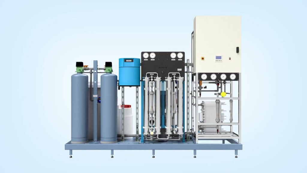
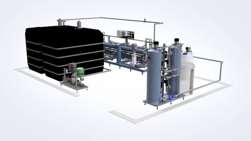
Figure 5 illustrates this general process configuration, while Figure 6 shows an example of such a system.
Case – Everfuel
One specific example of water treatment for green hydrogen production is the HySynergy project by Everfuel. Consisting of three phases – 20 MW (2022), 300 MW (2025) and 1 GW (2030), this project seeks to provide green hydrogen for both mobility and industrial end users. For the first phase, an alkaline electrolyser was chosen, requiring a flow of ultrapure water of 4.5 m3/h with a conductivity of <5 µS/cm. The water was sourced from the drinking water network with a hardness of 11°dH and no free chlorine. In this case the quality criteria could be met using a double-pass RO system combined with CO2 removal and with an ion exchange softener in front of the RO membranes to ensure very low concentration of multivalent ions.
Internal polishing of water
For electrolyser systems like PEM and AEM operating directly on ultrapure water, water treatment does not stop with the make-up water. After entering the electrolyser system, the water is continuously contaminated with metal ions from the piping and process equipment as well as with ions and organics from the electrolyser stack. These contaminants must be removed to maintain the lifetime of electrolyser.
The way to solve this problem is to introduce a side stream polisher internally in the electrolyser on the anode circulation system.
Two processes are available for handling the side stream polishing: mixed bed ion exchange and EDI. In this application, EDI is limited due to operational temperatures and the fact that it produces a concentrate waste stream. Mixed beds are the preferred option because they allow for zero waste of water and a higher flexibility in meeting the process requirements of the electrolyser system.
The side stream loop should be dimensioned to remove contaminants at a rate equal to or higher than the release rate to avoid accumulation in the electrolyser. The release rate is complicated to estimate as it depends both on material choices in the process equipment and the electrolyser as well as on operating conditions. Typically, the flow of the polisher loop will be in the range of 2–10% of the anode circulation flow rate. The higher the percentage, the higher the quality of the water sent to the electrolyser will be.
Pumps
Finally, we must also address the need for pumping and the effect it has on water quality. Pumps are used in several places in electrolyser systems, but the most central role is for circulation over the electrolyser stack. Large amounts of heat and gasses are released during electrolysis, and to remove gasses and maintain an acceptable temperature differential across the stack, very high flow rates are required. To keep the temperature increase between 2–4°C, a flow rate of 50–100 m3/h per MW is required. That means that the flow rate is 250–500 times larger than the flow of make-up water into the electrolyser system. Because of this, pumps take up a significant part of the CAPEX for a green hydrogen system, 10–20% of the combined CAPEX for stack components and balance of plant, and this presents operators with a difficult challenge. The cost of pumps pushes for cost-effective solutions, but the strict quality requirements as well as the harsh operating conditions push for high-quality and specialised products. Part of the solution to this challenge is to adopt a holistic approach and think about water treatment in combination with pumping. By improving the polishing system, the polisher can help overcome the release of metals and thus lower the requirements for the pumps used for recirculation.
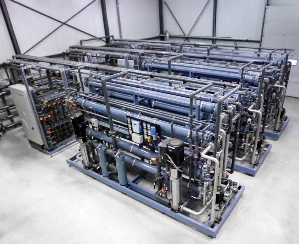
Looking ahead, it is clear that water treatment will play an essential role for the green hydrogen industry, and like the other components in a green hydrogen plant, water treatment systems will also face important questions about scalability, modularity, redundancy, etc. as the industry matures. Figure 9 shows an example of what such large-scale installations could look like.
About the author

Henrik Tækker Madsen, PhD, is a water treatment specialist working within the interplay between water and energy. He works as Application Development Manager at the water treatment company Silhorko-Eurowater A/S – part of Grundfos, where he leads the work on establishing industry-leading knowledge within various water applications, including electrolysis. Dr. Madsen is a chemical engineer with more than 10 years of experience in business development, sales, R&D and innovation.


